Requirements and modifications for running prjmod
Follow the instructions with great care.
Everything except NLS and Map switching is absolutely mandatory, you can not do any tuning before the steps are completed.
Supported ECU part numbers
Only the following control units are supported. They are all identically suited for running prjmod firmware. Make sure you have one (for obvious reasons).
- 4A0907551AA
- 4A0907551B
- 4A0907551C
- 4A0907551D
- 4A0907551E
- 4A0907551F
- 4A0997551X
- 4A0997551AX
- 4A0997551BX
- 4A0997551CX
- 4A0997551DX
- 4A0997551EX
- 895907551A
- 895907551B
- 895997551X
- 895997551AX
- 8A0907551B
- 8A0907551C
- 8A0997551X
- 8A0997551BX
OBD Interface
Any KKL cable will work, also the non-current generation Ross-Tech HEX+CAN cables with the USB pass-through driver installed. I recommend setting the COM-port latency to 1 in device settings.
MAP sensor
You need the MPXH6400A MAP sensor. It is possible to use any sensor, but unless you need to run more than 2.8 bar boost, save yourself the trouble, and run the MPXH6400A, as the provided basefiles are calibrated for it.
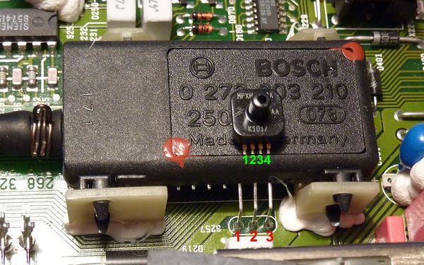
The following image shows the sensors on top of each other, incl. the pin numbering:

The pinouts are not 1:1, here is a table as to how they should be connected:
| Board | MPXH6400A |
| 1 | 2 |
| 2 | 4 |
| 3 | 3 |
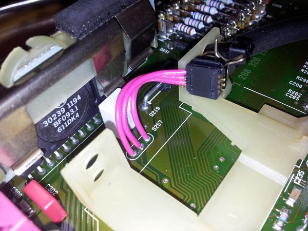
- Desolder and cut the old sensor off the rubber hose with an exacto knife, make sure to cut right past the nozzle, or you will need a new hose.
- Re-use the clip.
- Use a cable tie to secure the sensor in place.
- Make sure that the edge of the upper half of the MAP sensor package is "behind" the ledge of the white bracket, so the sensor can not be pushed out by pressure. Failing that use heat resistant glue.
Speed Density modifications
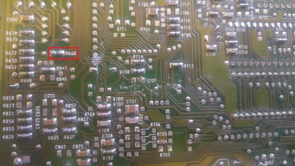
Remove 0 ohm resistor R660.

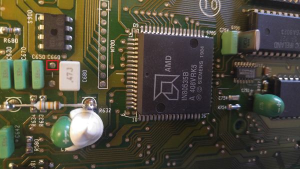
Remove solder from the via under "S900" chip. The via is directly under the writing "C660". Attach one end of wire through hole, the wire will go from one PCB to the other.

Remove solder from the via directly to the right of D232 (towards D235). Attach second end of wire through hole.

As the fuel/ign chip does not have a MAP connection, we are simply routing the MAP signal into a free analog input.
Immobilizer bypass
On cars fitted with an immobilizer the K-line runs to the white immobox on the steering column (behind the dash), and then from the immobox to the diagnostic socket.
The immo box will block any communications it does not consider "kosher" by pulling the whole K-line LOW on the ECU side. It certainly does not want you to run comms at 187500 baud, so you will need to cut out the middle man if you want to use fast logging.
To get rid of it:
- Remove the immobox connector
- Find two green wires in the connector.
- Check continuity.
- One of the green wires will have continuity to the K-line in the 2x2 connector under the hood.
- The other of the green wires will have continuity to pin 55 on the ECU.
- Once you have found the two K-line "ends" cut them at the connector and connect them together, you can also discard the immobox.
- If you want a proper immobilizer, wire in a reed switch somewhere or install an alarm with immobilization function. If anyone wants to steal one of these cars they can simply swap the ECU for a non-immobilized one in 30 seconds and drive off. The prjmod firmware has immo disabled.
I will be grateful if anyone can provide some pictures of this process.
